
Individual hose record
KHJ2179 Hose Repair Specifications
Excavator · Case · CX130D LC · Control Valve
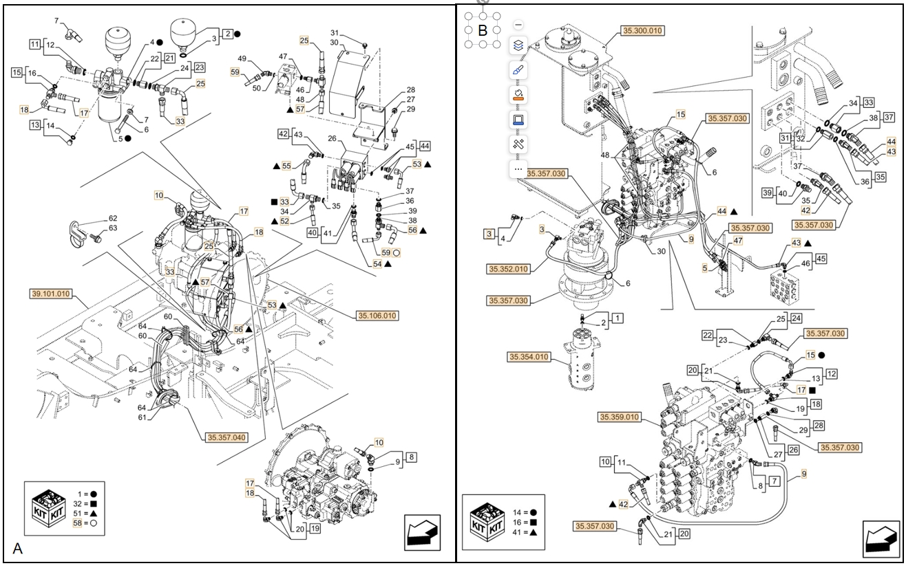
Locate this hose
Installation diagram — Pipe No. 15
Locate Pipe No. 15 in the diagram, then confirm part number KHJ2179 before removing the hose.
Repair specifications
- Part number
- KHJ2179
- Diagram pipe number
- 15
- Installation route
- 分配阀后~分配阀后
- Hose specification
- DN6;1SN-04;22.5MPa
- Finished length
- 450 mm
- Working pressure
- 22.5 MPa
- Left fitting
- British female thread, 60° external cone seatOriginal Chinese: 英制内螺纹60°外锥
- Right fitting
- 90° elbow, British female thread, 60° external cone seatOriginal Chinese: 90°英制内螺纹60°外锥
- Quantity
- 1
Workshop guide
Finding the correct hydraulic hose for Case CX130D LC Control Valve
Start with the machine and route
For Case CX130D LC Control Valve, identify the exact model and hydraulic system on the machine first. A part number or diagram pipe number is the fastest way to narrow a replacement hose; if neither is visible, compare the installation route and the existing hose.
Read the dimensions before cutting
Check whether a listed dimension is finished assembly length, hose-only length, or cut length. These are not interchangeable. Confirm hose specification and pressure rating, then compare both ends separately: thread, sealing seat, size, angle, and orientation.
Records to compare
- KHJ2179450 mm · DN6;1SN-04;22.5MPa · 分配阀后~分配阀后
Use the drawing as a location check
Where an installation drawing or manual figure is available, match its callout to the part number and physical route. A hydraulic circuit diagram explains connections but does not show the exact routing of a hose on the machine. Take the old hose or clear end-fitting photographs to the workshop if any dimension is missing.
For reference only. Confirm the actual hose before fabrication.