
- Length
- 2,650 mm
- Specification
- DN10;-6;10.3Mpa
- Left fitting
- 美制内螺纹37°锥
- Right fitting
- 美制内螺纹37°锥
Individual hose record
4I-1413 Hose Repair Specifications
Excavator · Caterpillar · CAT®317-A N · Control Lever
Finished length2,530 mm
Locate this hose
Installation diagram — Pipe No. 55
Locate Pipe No. 55 in the diagram, then confirm part number 4I-1413 before removing the hose.
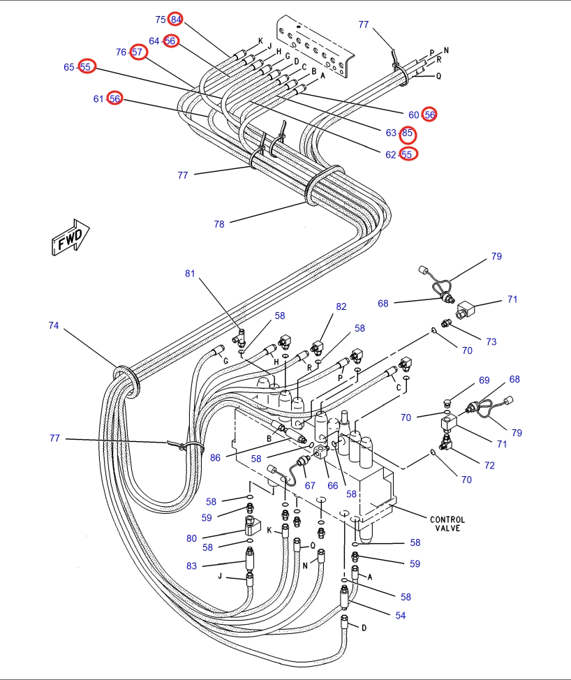
Repair specifications
- Part number
- 4I-1413
- Diagram pipe number
- 55
- Installation route
- 中转接头~分配阀上
- Hose specification
- DN10;-6;10.3Mpa
- Finished length
- 2,530 mm
- Working pressure
- 10.3 MPa
- Left fitting
- 美制内螺纹37°锥
- Right fitting
- 美制内螺纹37°锥
- Quantity
- 2
Same system
Related Hoses
- Length
- 2,360 mm
- Specification
- DN10;-6;10.3Mpa
- Left fitting
- 美制内螺纹37°锥
- Right fitting
- 美制内螺纹37°锥
Diagram Pipe No. 56
5I-3127
Installation route: Intermediate adapter → control valveOriginal Chinese: 中转接头~分配阀
- Length
- 1,900 mm
- Specification
- DN10;-6;10.3Mpa
- Left fitting
- 美制内螺纹37°锥
- Right fitting
- 美制内螺纹37°锥
Workshop guide
Finding the correct hydraulic hose for Caterpillar CAT®317-A N Control Lever
Start with the machine and route
For Caterpillar CAT®317-A N Control Lever, identify the exact model and hydraulic system on the machine first. A part number or diagram pipe number is the fastest way to narrow a replacement hose; if neither is visible, compare the installation route and the existing hose.
Read the dimensions before cutting
Check whether a listed dimension is finished assembly length, hose-only length, or cut length. These are not interchangeable. Confirm hose specification and pressure rating, then compare both ends separately: thread, sealing seat, size, angle, and orientation.
Records to compare
- 4I-14132,530 mm · DN10;-6;10.3Mpa · 中转接头~分配阀上
Use the drawing as a location check
Where an installation drawing or manual figure is available, match its callout to the part number and physical route. A hydraulic circuit diagram explains connections but does not show the exact routing of a hose on the machine. Take the old hose or clear end-fitting photographs to the workshop if any dimension is missing.
For reference only. Confirm the actual hose before fabrication.